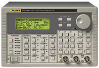
| 271 DDS Function Generator with ARB |
 |
|
| Waveforms |
| Frequency |
| |
All waveforms are available up to 10 MHz. However, the purity of triangle, ramp, and multi-level square wave waveforms is not specified above the frequencies indicated in the following section. |
| Range |
0.1 mHz to 10 MHz |
| Resolution |
7 digits or 0.1 mHz |
| Accuracy |
Typically < ± 10 ppm for 1 year, 18 °C to 28 °C |
| Tempco. |
Typically < 1 ppm/°C outside 18 °C to 28 °C | |
| Sinewave |
| Distortion |
< –60 dBc to 20 kHz, < –50 dBc to 300 kHz, < -35 dBc to 10 MHz |
| Spurii |
Non -harmonically related spurii typically <- 60 dBc to 10 MHz | |
| Squarewave |
| Rise and fall times |
< 22 ns | |
| Triangle |
| Linearity error |
< 0.5 % to 30 kHz | |
| Positive and Negative Ramp |
| Linearity error |
< 0.5 % to 30 kHz | |
| Positive and Negative Pulse |
| Rise and fall times |
< 22 ns | |
| Multi-Level Squarewave |
| |
Up to 16 steps available per cycle, each step selectable for amplitude (10 bit resolution) and duration (1 to 1024 samples). Above 27 kHz a 36 ns edge uncertainty is introduced. |
| Rise and fall times |
< 22 ns | |
| Arbitrary (and complex) |
| |
A number of “complex” waveforms are pre-programmed in ROM . A further five, user defined, waveforms may be loaded via the digital interfaces and stored in non-volatile RAM. Frequency range: All waveform points can be continuously output up to 27 kHz, beyond which they are sampled. |
| No. of samples |
1024 10 bit samples |
| Noise |
Wideband noise with variable amplitude and offset. | |
| Symmetry |
| Range |
Sine — 1 % to 99 % at all frequencies; Other waveforms — 1 % to 99 % to 30 kHz, |
| |
20 % to 80 % to 10 MHz |
| Resolution |
0.1 % | |
| Main Output |
| Output impedance |
|
| Amplitude |
| |
5 mV to 20 V pk-pk open circuit (2.5 mV to 10 V into 50 Ω/600 Ω). Output can be specified as V-H: 2 |
| |
(open circuit value) or V (Voltage into the characteristic impedance) in pk-pk, RMS or dBm. |
| |
Note that in positive or negative pulse modes the amplitude range is 2.5 mV to 10 V pk-pk O/C. | |
| Accuracy |
| |
Typically ±3 % ±1 mV at 1 kHz into 50 Ω/600 Ω | |
| Flatness |
| |
±0.2 dB to 500 kHz; ±1 dB to 10 MHz | |
| Pulse aberrations |
|
| DC offset |
| |
± 10 V from 50Ω/600 Ω offset plus signal peak limited to ± 10 V from 50 Ω/600 Ω | |
| Resolution |
| |
3 digits or 1 mV for both amplitude and offset | |
| Modulation |
| Amplitude Modulation |
| Carrier frequency |
0.1 mHz to 10 MHz |
| Carrier waveforms |
All |
| Depth |
0 to 100 %, resolution 1 % |
| Internal source |
1 kHz fixed sinewave or 0.005 Hz to 50 kHz square wave |
| External |
See “VCA In” section | |
| Frequency Shift Keying (FSK) |
| |
Phase coherent switching between two frequencies at a rate defined by the switching signal source |
| Carrier frequency |
0.1 mHz to 10 MHz |
| Carrier waveforms |
All |
| Switch repetition rate |
dc to 50 kHz internal, dc to 1 MHz external |
| Switching signal source. |
Internal from keyboard or trigger generator. External from EXT TRIG input or remote interface | |
| Operating Modes |
| Trigger/burst |
| |
Phase coherent signal keying — each positive edge of the trigger signal will produce one burst of the carrier, starting and stopping at the phase angle specified by the start/stop phase setting |
| Carrier frequency |
0.1 mHz to 10 MHz |
| Carrier waveforms |
All |
| Number of cycles |
1 to 1023 (resolution 1 cycle) or 0.5 to 511.5 (resolution 1/2 cycle) |
| Trigger rep. rate |
dc to 50 kHz internal, dc to 1 MHz external |
| Source |
Internal from keyboard or trigger generator. External from EXT TRIG input or remote interface | |
| Gated |
| |
Non phase-coherent signal keying — output is On while Gate signal is high and Off while low. |
| Carrier frequency |
From 0.1 mHz to 10 MHz |
| Carrier waveforms |
All |
| Trigger rep. rate |
dc to 50 kHz internal dc to 1 MHz external |
| Gate source |
Internal from keyboard or trigger generator. External from EXT TRIG input or remote interface | |
| Sweep |
| Carrier waveforms |
All |
| Sweep mode |
Linear or logarithmic, single or continuous |
| Sweep width |
0.1 mHz to 10 MHz. Phase continuous. Independent setting of the start and stop frequency. |
| Sweep time |
10 ms to 999 s (3 digit resolution) |
| Markers |
Two markers variable during sweep. Available at the TRIG/SWEEP OUT socket |
| Sweep trigger source |
The sweep may be free run or triggered from: keyboard, EXT TRIG input, remote interface | |
| Hop |
| |
Up to 16 different “hop” waveforms can be defined in terms of function, frequency, amplitude, offset and duration. Duration setable per step 1 ms to 60 s. | |
| Start/Stop Phase |
| Carrier frequency |
0.1 mHz to at least 1 MHz |
| Carrier waveforms |
All |
| Range |
–360 to +360 degrees |
| Resolution |
1 degree |
| Accuracy |
Typically 1 degree to 30 kHz | |
| Trigger Generator |
| |
Internal source 0.005 Hz to 50 kHz squarewave adjustable in 20 us steps. 3 digit resolution. Available for external use from TRIG/SWEEP OUT socket. | |
| Auxiliary Outputs |
| Aux Out |
| |
CMOS/TTL levels with symmetry and frequency of main output and phase of start-stop phase setting | |
| Trig/Sweep Out |
| |
Multi-function output depending upon mode. Except in sweep mode, the output is that of the trigger generator at CMOS/TTL levels from 1 kW. |
| |
In Sweep mode the output is a 3-level waveform, changing from high (+4 V) to low (0 V) at the start of sweep, with narrow 1 V pulses at each marker point. | |
| Inputs |
| Ext Trig |
| Frequency range |
DC to 1 MHz |
| Signal range |
TTL (1.5 V) threshold; maximum input ± 10 V |
| Min. pulse width |
50 ns | |
| VCA In |
| Frequency range |
DC - 100 kHz |
| Signal range |
2.5 V for 100 % level change at maximum output |
| Input impedance |
Typically 6 kΩ | |
| Phase Locking |
| Clock in/out |
| |
TTL/CMOS threshold levels; output impedance typically 50 Ω as an output | |
| Sync out |
| |
TTL/CMOS logic levels from typically 50 Ω. The signals from these sockets are used to phase lock two or more generators. | |
| Interfaces |
| RS-232 |
| |
Variable Baud rate, 9600 Baud maximum. 9-pin D-connector. | |
| IEEE-488 |
| |
Conforming with IEEE488.1 and IEEE488.2 | |
| General Specifications |
| Display |
| |
20 character x 4 row alphanumeric LCD | |
| Data entry |
| |
Keyboard selection of mode, waveform etc.; value entry direct by numeric keys or by rotary control. | |
| Stored settings |
| |
Up to 9 complete instrument set-ups may be stored and recalled from battery-backed memory. | |
| Size |
| |
3U (130 mm) height; half-rack (212 mm) width, 330 mm long | |
| Weight |
|
| Power |
| |
100 V ac, 110 to 120 V ac or 220 to 240 V ac +/– 10 %, 50/60 Hz ac by internal adjustment; 30 VA max. | |
| Operating range |
| |
+5 °C to 40 °C, 20 to 80 % RH | |
| Storage range |
|
| Options |
| |
IEEE-488 interface; 19-in rack mounting kit | | | |